
What is an encoder?
An encoder is one type of instrument used in Process control and Instrumentation. See more on the topic of Control and Instrumentation by clicking >here<.
One definition of an encoder is: a device that converts motion into a sequence of digital pulses. These pulses can be used to determine relative or absolute position. Rotary encoders is the most common type of encoder, but linear types are also available on the market.
 |
| Figure 1 |
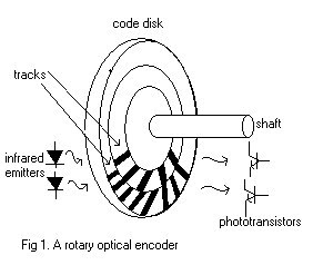
Here are some illustrations of the construction of rotary encoders:
The code-disc is usually constructed with glass or plastic and has “blacked out parts”, and clear parts which will let through the light from a light source (or infrared emitters). In most cases these clear and “blacked out” parts are arranged radially in tracks, as shown in figure 2.
The optical sensor (or photo transistors or photo-elements) will generate digital pulses as the light source is blocked off or let through at different sections of the code-disc as the shaft rotates.
Encoder Designs
 |
| Figure 2 |
There are two basic designs when it comes to encoders: the Absolute encoder and the Incremental encoder (or relative encoder).
The absolute encoder has a code-disc as shown in figure 2. This encoder produces words which corresponds to N number of sections on the disc. For example, if the disc has 4 tracks it can have 16 different unique positions with a radial resolution of 360/16 = 22.5 degrees. This is not very accurate, but serves as an easy example. Naturally the accuracy will increase with more tracks.
In other words, with 8 tracks, there will be 256 possible unique positions which produces a resolution of 1.406 degrees.
Getting back to our example of 4 tracks : the most commonly used numerical encoding used in absolute encoders are binary- or gray code, shown in the two illustrations below. Here the layout of the code-disc is shown in rectangular form and then output from the photo elements. Note that MSB is the “Most Significant Bit” and LSB is the “Least Significant Bit”.
 |
|
| Figure 3 |
 |
||||||||||||
| Figure 4 |
Here is a table of the progressing rotation in degrees compared to the output of the encoder. Note that gray code was designed so that only one bit will change from one sector the another:
| Decimal code | Rotation range (deg.) | Binary code | Gray code |
| 0 | 0-22.5 | 0000 | 0000 |
| 1 | 22.5-45 | 0001 | 0001 |
| 2 | 45-67.5 | 0010 | 0011 |
| 3 | 67.5-90 | 0011 | 0010 |
| 4 | 90-112.5 | 0100 | 0110 |
| 5 | 112.5-135 | 0101 | 0111 |
| 6 | 135-157.5 | 0110 | 0101 |
| 7 | 15.75-180 | 0111 | 0100 |
| 8 | 180-202.5 | 1000 | 1100 |
| 9 | 202.5-225 | 1001 | 1101 |
| 10 | 225-247.5 | 1010 | 1111 |
| 11 | 247.5-270 | 1011 | 1110 |
| 12 | 270-292.5 | 1100 | 1010 |
| 13 | 292.5-315 | 1101 | 1011 |
| 14 | 315-337.5 | 1110 | 1001 |
| 15 | 337.5-360 | 1111 | 1000 |
Uncertainty with binary
 |
|
| Figure 5 |
The incremental encoder
(also known as a relative encoder) has a simpler design than the aforementioned absolute encoder. A basic design only has two tracks and two sensors of which the output is called the A and B channels. In some cases there is also a third channel called the INDEX which gives one pulse per rotation.
In Figure 5 it can be seen that the code-disc is designed in such a way that the one channel leads the other by a 1/4 rotation. The direction of rotation is obtained by monitoring the relationship of the pulses created by each channel and the speed is obtained from the frequency of the pulses.
By counting the pulses and knowing the resolution of the disk, the angular motion can be measured. When the third channel is present in the design, it is useful for determining the zero position of the encoder and to count full revolutions.
===
Encoders, and servo’s (covered in: “What is a servo?”) are some of the corner stones of Control and Instrumentation.
Thank you for vising THE STEM BLOG SA
Click on Subscribe, share or simply look me up on any of these networks:
![]()
![]()
![]()
![]()
![]()
Great information, I bookmarked this and will definitely be returning to it later when I am setting up encoders.
awesome, but lacks details. please also add the respective derivations and formulae.